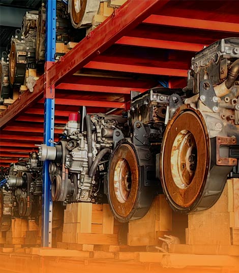
When the owner of a 20-ton-class hydraulic excavator searches for one cooling-system part by itself, ready to stop a temperature needle that climbs into the red on every heavy dig, a coolant level that drops a little each shift, a damp streak down the front of the engine, a squeal from the belt drive, or a radiator that stays cold while the head gets hot, the engine water pump is one of the highest-demand single parts in the excavator aftermarket. The water pump is the only driven element that moves coolant through the block, the head and the radiator; everything else in the circuit – the thermostat, the hoses, the fan, the radiator core – can only work with the flow the pump creates. When a pump loses its mechanical seal, cavitates its impeller, scores its shaft, or loosens its bearing under a mis-tensioned belt, the machine begins to overheat under load, weeps coolant from the vent hole, growls at the front of the engine, or boils over until a modest pump and coolant job becomes a head-gasket, liner and radiator overhaul. This field guide is about that one part, using the catalog reference 3802081 as a representative engine water pump for a 20-ton-class hydraulic excavator: what it does, how it is built, why it fails, how to read the early warnings, how to tell a pump fault from a thermostat or radiator fault, how to measure it, and how to choose and fit a replacement that restores circulation instead of repeating the fault. The reference 3802081 is used here as a representative catalog reference for this class of part; no equipment or component brand is named, only the reference the machine reads.
The demand signal behind the search is easy to read. Overheating is the single most common reason an excavator is parked in warm weather, and field troubleshooting almost always walks the same path: clear the radiator fins, check the fan belt, test the thermostat, inspect the coolant, and only then condemn the pump. That sequence is why water-pump searches are so steady – the pump is the last component checked but the one most often replaced once the cheap fixes have been tried. A pump search usually means a symptom already exists: a slow drip from the weep hole, a wobbling pulley, a temperature that rises only under load, or a heater that blows cold at idle. It is a higher-stakes single part than a hose clamp, because a failed pump can warp a head in one long shift. The search signal here is about flange pattern, impeller diameter, pulley offset, shaft length, seal type and port orientation – not just availability. Buyers who search by the reference 3802081 are usually trying to answer one question: will this pump bolt to my engine, line up with my belt, and move the volume my cooling circuit needs.
What the Engine Water Pump Does and Where It Sits
Position in the Coolant Circuit
The water pump bolts to the front of the engine block, driven by the accessory belt from the crankshaft pulley, and it pushes coolant into the block where the liquid climbs around the cylinder liners, rises through the head, and returns to the radiator through the thermostat housing. Most cooling circuits on this weight class run the pump as a centrifugal unit with a cast housing, a pressed-on impeller, a shaft carried in a sealed double-row bearing, and a mechanical face seal that keeps coolant on one side and bearing grease on the other. A small vent or weep hole sits between the seal and the bearing, open to atmosphere, so the first sign of a seal leak is a drip rather than a flood into the bearing. Understanding that lay-out matters because the pump is not a pressure source in the way a hydraulic pump is: it is a flow source. Its job is to keep enough coolant moving past hot metal that the radiator always sees a temperature difference it can reject. If flow falls, the radiator may be perfectly clean and the fan may be spinning at full speed, yet the head still overheats because the heat is never carried out of the iron.
Why the Reference 3802081 Is Searched
The reference 3802081, like every water pump reference, is the key that unlocks one specific combination of mounting flange, bolt circle, inlet and outlet port position, impeller diameter and vane count, shaft length, pulley offset, belt groove count, seal diameter and housing depth for one engine configuration. It is not a cosmetic label; it tells the supplier which block face the pump seals against, how far the pulley sits from the mounting plane, whether the drive uses a single or double groove, which thermostat housing bolts to the outlet, and how deep the impeller sits in the volute. Reading the reference against the machine weight class and the engine serial break is the only reliable first step, because a pump from the wrong family may bolt to the block yet place the pulley a few millimetres out of line, rub the impeller on the housing, or put the outlet where the hose cannot reach. For a 20-ton-class hydraulic excavator, the reference 3802081 points to a pump sized for the coolant volume and heat rejection of that operating-weight band, and that sizing – not the outer silhouette – is what decides flow, belt alignment and seal life. Confirm the reference on the old housing or the machine record before ordering, because two visually similar pumps can differ in shaft length by a few millimetres and still be completely incompatible.
How a Water Pump Is Built
Housing, Impeller and Drive Flange
The housing is usually cast iron or cast aluminium, machined on the block face and shaped internally into a spiral volute that converts impeller velocity into usable flow. The impeller sits on the inner end of the shaft and is either stamped steel, cast iron, or a moulded polymer, with six to ten curved vanes that pull coolant in at the eye and fling it outward into the volute. Impeller diameter and vane geometry set the flow curve, and even a small reduction in diameter or a few millimetres of vane erosion can cut delivered volume enough to matter at full load. The drive flange on the outer end of the shaft carries the pulley, and its offset from the mounting face is what keeps the belt in one plane with the crankshaft and alternator pulleys. A flange that sits too far forward or too far back loads the belt sideways, which shortens belt life and hammers the pump bearing from a direction it was never designed to take. For a 3802081-class pump, the housing depth, the impeller diameter and the flange offset are a matched set, and changing one without the others breaks the alignment that the engine was built around.
Shaft, Bearing and Mechanical Seal
Inside the housing, a hardened steel shaft runs in a double-row ball bearing that is permanently lubricated and sealed for life. The bearing carries radial load from the belt tension and axial load from the impeller, and it is the component that decides whether the pump runs quietly for a full service interval or develops a rumble within a few hundred hours. On the coolant side of that bearing sits the mechanical seal: a stationary ceramic or carbon ring pressed into the housing, a rotating ring carried on the shaft, and a spring that holds the two lapped faces together with a thin coolant film between them. That film is the whole design – enough liquid to lubricate the faces, not enough to leak. Abrasive rust, scale crystals, or seal-face grooving destroy the film, and once the faces run dry they score, overheat and crack. The shaft must be straight, the bearing must hold its clearance, and the seal faces must stay lapped and undamaged; a single nicked face lets coolant past, and coolant past the seal reaches the bearing and washes out its grease. A pump quoted only as a housing with an impeller is an incomplete assembly, because the shaft, the bearing and the seal are the parts that decide whether it survives.
Reading the Early Warning Signs
Coolant at the Weep Hole
A visible drip is the most specific warning a water pump can give, and it should be graded rather than ignored. A few drops on a cold morning after a long shutdown can be a seal that has not yet wetted; a continuous drip at idle, a stream that increases with engine speed, or a spray from the pulley area points to a failed face seal and a pump that has already lost its grease barrier. The colour of the deposit is useful too: clean coolant leaves a light crystalline trace, while rusty brown residue says the cooling system is carrying corrosion products that will abrade the next pump just as quickly. Any drip should trigger two decisions at once: replace the pump, and find out why the seal failed. A seal that dies early is usually a symptom of exhausted inhibitor, wrong coolant mix, an over-tight belt, or a system that has been run with plain water. Fitting a new 3802081-class unit into the same contaminated circuit simply restarts the clock on the same failure.
Noise, Wobble and Belt Dust
Bearing wear announces itself in sound and movement before it announces itself in temperature. A dry or spalled bearing gives a low rumble or a rhythmic chirp that follows engine speed, often loudest at the front of the engine with a screwdriver used as a listening rod. As clearance grows, the pulley begins to rock: with the engine stopped and the belt slackened, grasping the pulley and rocking it should produce no perceptible play and no gritty feel when rotated. Any side play, any notchiness, or a scrape that comes and goes once per revolution means the bearing is finished. Black rubber dust collecting under the pump pulley is another clue, because a wobbling pulley or a misaligned belt shears the belt edges and grinds them into powder. That dust is often blamed on a cheap belt, but a new belt on a wobbling pump will be dusted again within hours. The pump, the tensioner and the alignment should be checked together.
Temperature Behaviour Under Load
Where a pump loses flow rather than sealing, the temperature trace is the main evidence. A healthy circuit warms to thermostat opening temperature and then holds within a narrow band, rising slightly on a long hard dig and falling back quickly at idle. A flow-starved pump tends to hold a normal temperature at light work and then climb steadily and continuously once the hydraulic system is loaded, with the gauge falling slowly rather than snapping back when the load comes off. The radiator inlet hose may be hot while the outlet stays surprisingly cool, and the cab heater may deliver little heat at idle because there is not enough circulation to push coolant through the heater core. An infrared thermometer is more reliable than the dash gauge here: compare the head outlet, the radiator inlet and the radiator outlet after a loaded run. A large drop across the radiator with a climbing head temperature says heat is being rejected but not carried; a small drop with both ends hot says airflow or core condition is the limit.
Why Water Pumps Fail
Seal Face Wear and Coolant Quality
Most water pumps do not wear out in the abstract; they are killed by the liquid they are asked to pump. Coolant is a mixture of water, glycol and an inhibitor package, and the inhibitor is consumed over time. Once it is gone, the liquid becomes acidic, dissolved oxygen attacks the iron and aluminium surfaces, and rust and scale crystals circulate as a fine abrasive slurry. Those crystals are exactly the right size to score the lapped faces of a mechanical seal, and once scored, the seal cannot hold its film. Plain water is worse: it raises the boiling point only marginally under pressure, carries dissolved minerals that plate out as scale on the hottest surfaces, and offers no corrosion protection at all. A machine topped up with water after every small leak will destroy a new pump in a fraction of its intended life. This is why a pump replacement and a full coolant renewal belong in the same job, and why the drain, flush and refill steps are not optional extras.
Cavitation and Impeller Erosion
Cavitation is the formation and violent collapse of vapour bubbles at the impeller eye, and it is the mechanism that eats impeller vanes without any external sign. It happens when suction-side pressure falls below the vapour pressure of the hot coolant: a restricted inlet hose, a collapsed hose liner, a partly closed valve, an undersized or clogged bypass, a weak pressure cap, or an overheated system can all push the circuit into that condition. Each collapsing bubble strikes the vane surface with a tiny but intense shock, and over hundreds of hours the metal is pitted, then perforated, then thinned until the vane breaks away. The pump still turns, still holds coolant, and still looks sealed, but delivered volume collapses. Operators often describe this as the pump suddenly giving up after a hot week, when in fact the damage accumulated quietly over a whole season. A pitted, sandblasted look on the old impeller is the post-mortem signature.
Bearing Overload from Belt Tension
The pump bearing is sized for a defined belt load, and that load is easy to exceed. A belt tensioned by eye with a long breaker bar, an automatic tensioner that has seized at full travel, or a pulley that is out of plane with the crankshaft all apply a steady radial force far above the design value. The bearing then runs hot, its grease thins and migrates, the balls begin to skid rather than roll, and the races spall. Failure follows in a few hundred hours, and the new pump inherits exactly the same overload if the drive is not corrected at the same time. Belt alignment is as important as tension: a pulley offset by even a small amount makes the belt climb the groove and side-loads the shaft in a direction the double-row bearing was not intended to carry. Black dust beneath the pulley, a glazed belt edge, or a belt that tracks to one side are all evidence of alignment trouble rather than a belt quality problem.
Diagnosing Overheating Without Guessing
Separate the Pump from Thermostat, Radiator and Fan
A disciplined diagnosis saves more money than any part. Start with the cheap and external: look through the radiator core from the engine side, clear fins with low-pressure air or a soft brush rather than a pressure washer, confirm the fan shroud and any foam seals are in place, and check that the fan turns at the expected speed when hot. Then test the thermostat by watching the upper hose and measuring the housing temperature as the engine warms; a unit stuck shut sends the head temperature up fast while the radiator stays cold, and a unit stuck open keeps the engine too cool and slow to warm. Check the cap with a tester, check the coolant concentration with a refractometer, and inspect the hoses for collapse under suction. Only after those are cleared does the pump become the prime suspect. Working in this order avoids the common and expensive mistake of fitting a pump to a machine whose real problem was a dust-packed core.
Simple Bench and On-Machine Checks
A pump that has been removed can be checked on the bench in minutes. Turn the shaft by hand and feel for grit, notchiness or axial movement; look into the inlet and outlet for vane damage, casting flash and corrosion; inspect the seal seat through the weep hole with a bright light; and compare the old flange, bolt circle, port angle, pulley offset and impeller diameter directly against the replacement before any gasket sealant is applied. Laying the two units side by side on a clean bench catches most fit errors, including the subtle ones such as a pulley that sits a few millimetres further out. Spin the impeller with a finger through the inlet; it should turn freely with no scrape against the volute. Any doubt at this stage is far cheaper to resolve than after the housing is bolted to a cold block in the field.
Measuring and Matching the Reference 3802081
Dimensions That Decide Fit
Five dimensions decide whether a pump fits and works: the mounting flange shape and bolt circle, the distance from the mounting face to the pulley centreline, the impeller diameter and its depth in the volute, the inlet and outlet port diameters and their angles, and the shaft and seal diameter that determines which seal and bearing group is inside. A sixth, less obvious item is the thermostat housing interface, since on many engines the pump outlet forms half of that joint. Measure the old unit with a caliper and a straightedge rather than trusting a photograph: bolt spacing, flange thickness, hub height and pulley offset are the numbers that matter. Note also whether the drive pulley is single or double groove, and whether the pump is driven by the flat or the ribbed side of the belt. A mismatch in any one of these turns a correct-looking part into a machine that will not hold a belt or will not seal against the block.
Serial Breaks and Similar-Looking Pumps
Engine families evolve, and pump references change with them. A block casting may be revised, a pulley offset may move, a thermostat housing may be reshaped, or the drive may switch from a single groove to a double groove while the outside of the housing stays almost identical. That is why a serial break matters: the same machine model can carry two different pump references depending on when it was built, and a supplier who quotes by model alone will get it wrong perhaps half the time. The reliable identifiers are the reference stamped or cast on the old housing, the engine serial number, and the physical measurements taken from the old part. Where the old marking has been painted over or corroded away, a photograph of the mounting face, the pulley and the port angle sent with the order is far better than a description.
Choosing a Replacement Pump
Impeller Material and Seal Design
For a 20-ton-class excavator working long shifts in heat and dust, a cast-iron or high-grade stamped-steel impeller with a properly hardened shaft and a cartridge-style mechanical seal is the sensible specification. Cast iron resists cavitation pitting; hardened steel resists the abrasive slurry that exhausted coolant produces; and a cartridge seal keeps the lapped faces protected during storage and fitting in a way that loose components cannot. Ask specifically about the seal face material and the spring, about the bearing being sealed for life, and about the weep hole being open and correctly positioned. A pump with a plugged or missing vent is a pump that will hide its own failure. The gasket or O-ring supplied should match the machined face, and the fixing bolts should be of the correct length for the flange thickness; a bolt that bottoms out in a blind hole will crack the housing as readily as one that is left loose.
What a Complete Order Should Include
A water pump job is a system job, so the order should be built as a kit even when the pump is the headline item. Include the correct flange gasket or O-ring, a new belt, a fresh thermostat and its seal, a pressure cap if the existing one is of unknown age, the correct volume of concentrate or premix for a full refill, and any hose or clamp that shows softening or corrosion at the ends. If the engine uses a separate bypass hose or a small bleed line, add those too, because they are the parts most likely to fail a week after the system has been disturbed. Having everything on the bench before the drain plug is removed is what keeps a half-day repair from becoming a two-day wait. It also avoids the temptation to reuse a marginal old belt or a flattened gasket, which is exactly how a new pump gets blamed for an old fault.
Fitting the Pump Correctly
Preparation, Cleaning and Torque
Most flange leaks are created in the ten minutes before the new pump goes on. Drain the system fully, remove the old gasket without gouging the block face, and clean both mating surfaces until they are bright and flat; a thin film of old gasket or a burr around a bolt hole is enough to hold the housing off square. Check the block face with a straightedge, chase the bolt holes so a bolt cannot bottom on debris, and dry-fit the new pump with the gasket to confirm every hole lines up and the pulley sits in the belt plane. Apply sealant only where the gasket design calls for it, and never so much that it extrudes into the coolant passage. Tighten the bolts in a cross pattern in two or three stages to the specified torque, because an uneven pull on a cast flange can distort it or crack a boss. Turn the shaft by hand after tightening to confirm nothing has shifted.
Refill, Bleed and First Heat Cycle
With the system full, run the engine at a fast idle with the heater open and watch the level in the expansion tank as the thermostat cycles. The level will usually drop once as trapped air works its way out; top up to the cold mark, refit the cap, and bring the machine up to temperature under a moderate load. During this first heat cycle, check the weep hole every few minutes, feel both radiator hoses to confirm circulation has started, and measure the head outlet and radiator inlet temperatures. A healthy result is a stable, repeatable temperature band with no crawl upward at sustained load. Let the machine cool fully afterwards, recheck the level, recheck the belt tension and inspect the joint and the vent once more with a clean rag. Only after that cold recheck should the machine go back to full production work.
Preventing a Repeat Failure
Coolant Specification and Change Interval
Prevention begins with the liquid. Use one approved formulation at the specified concentration, made up with clean low-mineral water, and change it at the interval the engine maker specifies rather than when it looks dirty. Colour is not a condition test: an exhausted inhibitor can still look bright while offering no corrosion protection. A refractometer gives the freeze and boil margin, and simple test strips give an indication of inhibitor condition and pH. Keep the expansion tank at the correct level, because a low level draws air into the pump inlet on every cool-down and starts the cavitation cycle again. Never top up with plain water except in a genuine emergency, and if that ever happens, schedule a full drain, flush and refill as soon as the machine is back in the yard. The cost of a correct refill is trivial beside the cost of a second pump.
Belt, Tensioner and Radiator Care
The drive and the heat exchanger are the pump’s two neighbours, and both need to stay healthy. Inspect the belt for glazing, cracks and edge wear, check the tensioner for free movement and correct damping, and replace both as a matched pair at the specified interval or whenever a pump is renewed. Keep the pulley grooves clean and free of rust, because a rough groove abrades a new belt and raises the radial load on the bearing. On the air side, clean the radiator core with low-pressure air directed from the engine side outward, repair folded fins with a fin comb, and keep the shroud and seals intact so the fan pulls air through the core rather than around it. A clean core lowers the whole system temperature, which lowers the suction temperature at the impeller eye and moves the circuit away from cavitation.
Cost, Downtime and a Practical Decision Rule
What the Repair Really Costs
The price of the pump is the smallest line on a cooling repair. Labour to drain, flush, strip the drive, clean the flange, fit, refill, bleed and verify is several times the part cost, and lost machine hours on a working site are usually several times again. That ratio is why a cheap pump of uncertain internal specification is poor value: the saving is small, and a repeat failure pays the entire labour bill a second time. It is also why the kit approach makes economic sense. A gasket, belt, thermostat, cap and coolant bought with the pump add a modest amount to the invoice but remove the most common causes of a comeback, and they use the same opening of the system rather than creating a second one later. When the machine is already stopped, doing the whole cooling group once is nearly always cheaper than doing it in stages.
When to Replace and When to Keep Running
A workable decision rule is simple. A dry weep hole, a quiet bearing with no pulley play, a clean coolant of known chemistry, a stable temperature under sustained load, and a sensible temperature split across the radiator mean the pump stays. A steady drip, a rumble or any side play, a pitted impeller revealed by inspection, a temperature that climbs only under load after all the external causes have been cleared, or coolant of unknown age and type all mean the pump is renewed – and renewed together with the coolant, belt, thermostat, cap and gasket. There is no useful middle ground of additives and seal conditioners for a failed mechanical face seal; those products belong in an emergency that gets a machine off a site, not in a repair plan. Once the seal is scored, flow or sealing has already been lost.