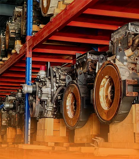
When an owner of a 20-ton-class hydraulic excavator searches for one hydraulic assembly by itself, ready to restore controlled movement to the boom, arm and bucket, the main control valve – the directional valve bank that splits the pump’s flow and directs it to each cylinder and motor – is one of the highest-demand single assemblies in the excavator aftermarket. The main control valve is the sealed manifold that turns raw pump pressure into the precise, proportional motion of every working function, and it holds the spools, relief valves and compensators that decide how fast and how strongly each actuator moves under load, dig shock and continuous duty every cycle. When a main control valve scores its bore, sticks a spool, bypasses internally or loses its compensator, the boom slows, the arm drifts, the bucket crawls, or the whole machine loses the crisp response that makes a cycle fast, and because the valve sits upstream of every working function, a weak main control valve is felt across the entire hydraulic group. This field guide is about that one assembly, using the catalog reference 20Y-62-11100 as a representative main control valve for a 20-ton-class hydraulic excavator: what it does, how it is built, why it fails, how to read the early warnings, how to measure it, and how to choose and fit a replacement that restores crisp, proportional control instead of repeating the fault. The reference number 20Y-62-11100 is used here as a representative catalog reference for this class of assembly; no equipment or component brand is named, only the reference the machine reads.
The demand signal behind the search is easy to read. A crawler excavator moves its boom, arm, bucket, swing and travel through a closed-center hydraulic circuit, and the main control valve is the junction where pump flow is split, prioritised and metered to each function under a load-sensing or pressure-compensated scheme, so it wears and fatigues in step with the hardest-working functions. Industry service data places a large share of excavator hydraulic complaints in the valve and pump circuits, and main-valve, spool and relief-valve searches are among the steadiest aftermarket queries, because the valve meters the entire working group and its spools, seals and compensators take the contamination and pressure spikes the rest of the circuit passes through. A main-control-valve search usually means a symptom already exists: a slow or weak cylinder, a function that drifts or creeps, a circuit that overheats, or a valve that has begun to stick. It is a higher-stakes single assembly than a hose or a filter, because a worn main control valve scatters the flow and pressure the whole working group depends on. The search signal here is about flow rating, sections, ports and spool type – not just availability.
What the Main Control Valve Does and Where It Sits
Position and the Load It Holds
The main control valve is mounted between the hydraulic pump and the working actuators, usually on the upperstructure near the pump and the main relief. Pressurised oil from the pump arrives at the inlet, the valve splits it across the boom, arm, bucket, swing and travel sections, and each spool meters how much flow and at what priority reaches its actuator. What matters for machine behaviour is that the valve holds its calibration and its seal across every stroke: a healthy unit lets each function accelerate, hold and reverse smoothly, because the valve is the axis that sets the speed and force of every dig and load move. It is the component that sets the ceiling on hydraulic responsiveness, and it does so with a bank of spools, a relief group and a compensator set that must survive pressure spikes, contamination and the side load of a machine that digs and slews all day. That is why the finish of the bores and the grade of the seals are not details – they are the difference between a valve that holds pressure and one that bypasses within a season.
Why the Reference 20Y-62-11100 Is Searched
The reference 20Y-62-11100, like every main-control-valve reference, is the key that unlocks the correct combination of flow rating, number of sections, port sizes and spool configuration for one machine configuration. It is not a cosmetic label; it tells the supplier which pump flow the body must pass, which number of working sections the harness and linkage demand, which port thread and size the hose runs require, and which spool type the compensator expects. Reading the reference against the machine’s weight class and serial break is the only reliable first step, because a main control valve from the wrong family will not accept the pump flow, will not match the hose ports, or will deliver the wrong priority and starve the rotating or travel group. For a 20-ton-class hydraulic excavator, the reference 20Y-62-11100 points to a main control valve sized for that operating-weight band, and that sizing – not the outer shape – is what decides fit and life.
How a Main Control Valve Is Built
Spool and Section Body
A main control valve is a bank of precision bored sections bolted into one body, each carrying a spool that slides to connect pump, actuator and tank. The pump flow enters the inlet manifold; each spool, moved by pilot pressure or by a mechanical linkage, opens a metered path to its actuator while the compensator holds the pressure drop across the spool constant so the speed stays proportional to lever travel. Under working pressure the spools, the bore seats and the relief springs carry tonnes of force through a compact casting, so the metal, the bore finish and the spool straightness decide whether the valve holds. A main control valve is built heavy against a hard job: a bank of spools asked to meter the entire working group, thousands of cycles a day, in dust, moisture and temperature swings. That is why the grade of the spool steel and the quality of the bore honing are not details – they are what keep the valve from bypassing and sticking within a season.
The Seal and Bore Package
The seals and bore surfaces are the parts that actually keep the valve alive. A complete main-control-valve service package is matched to one specific assembly, not to a size range: the O-rings and backups that close each section joint, the spool seals that stop bypass between ports, the compensator and relief seals that hold priority, and the end-cap and plug seals that close the body. The material matters as much as the fit – nitrile, fluorocarbon and specialised composites each behave differently under heat and contamination. A package quoted only as a spool seal is a package that will be fitted twice, because the compensator seals, the section O-rings and the backups are the parts that actually decide whether the valve holds. The reference number, not the body’s outer size, is the anchor for ordering the right package.
Reading the Failure Signals Early
Slow or Weak Cylinder Movement
The first and most obvious signal is motion loss. A function that extends slow, needs higher engine speed to move, or fails to lift under load names a loss inside the valve – a scored bore, a sticking spool, a failed compensator or a relief that has drifted open – and often there is no external leak at all. That internal loss quietly contaminates the hydraulic system and scatters the flow the working group depends on, because the oil that should drive the actuator is slipping across worn spool seats instead. An actuator that will not move smoothly is a power-loss signal as well as a control signal, and it points straight at the valve rather than the cylinder, especially when the cylinder itself measures sound.
Drift and Creep
The second signal is holding. A boom or arm that drifts down, a bucket that creeps open, or a swing that will not hold its angle names a spool or seal that is passing oil it should block. The valve’s holding sections are meant to lock the actuator when the lever is centred, and a worn spool seat or a tired seal lets the load bleed back to tank. Because the fault hides inside the valve body, it is easy to blame the cylinder seal first, but a pressure and flow check at the valve usually points back at the spool. Reading the drift as a main-control-valve signal rather than a cylinder fault is what turns a breakdown into a planned rebuild.
Overheat and Foam
The third signal is heat. A main control valve that bypasses internally, or a relief that chatters open under load, dumps pump flow back to tank as heat, and the circuit climbs past its safe temperature, foams and loses viscosity. Heat is the enemy of every seal in the machine, so a valve that runs hot is quietly ageing the entire hydraulic group. A circuit that overheats under normal work, with no obvious external leak, is a strong main-control-valve signal, and it names a compensator or relief fault that will not heal on its own.
Abnormal Noise
The fourth signal is sound. A main control valve that howls, chatters or knocks under load is telling you the compensator or relief is in distress – a sticking compensator, a chattering relief spring or cavitation from a starving inlet. A chatter on every lever pull is not background noise; it is the valve transmitting pressure instability straight to the pump, and it names a fault that will not heal. A valve that has begun to sing needs teardown before the failure spreads to the pump, because a damaged main control valve can damage the pump it feeds.
Diagnose Before You Buy
The Key Measurements
The first discipline in main-control-valve service is to measure before ordering. Confirm the inlet and outlet port sizes and threads, the number and arrangement of working sections, the pilot or mechanical actuation type, the overall mounting and bolt pattern, the relief and compensator settings, and the spool type and travel. Flow rating and porting can vary even between consecutive serial ranges of the same model, so never assume from the badge alone; measure or verify against the reference. A seal kit or a spool for an excavator does not exist as a generic size – every valve is built for one specific flow, port and spool configuration, and fitting a travel or swing valve into a main position is the classic rebuild mistake because the porting and flow differ.
Valve Versus Pump Versus Cylinder
Separate the valve problem from the pump problem from the cylinder problem. A leak at a hose connection is not necessarily a valve failure, and a drifting function can involve a cylinder seal rather than the spool. A main control valve that ate its compensator rarely did so without help – contamination, a strained relief or a cavitating inlet will kill the next set too. The right decision compares technical condition, teardown evidence, downtime, risk of recurrence and actual cost, rather than using the price of a spool seal as the only yardstick. If the body is sound and only the spools and seals are worn, a seal and spool kit is enough; if the bore is scored or the compensator is damaged, the valve body must be dealt with first.
Repair, Rebuild, or Replace
When a Seal and Spool Kit Is Enough
Rebuild with a seal and spool kit when only the seals, wipers and sliding elements are damaged, the spools measure within tolerance, and the bore shows no scoring or bell-mouthing. The kit is a small cost, the valve is reseated with new section and spool protection, and the repair is measured in hours. On a machine whose functions still move true and hold their load, a quality kit matched to the reference restores the valve to full service for a fraction of a replacement cost.
When to Rebuild the Sections
Rebuild the sections when the sliding elements are worn but the body casting is sound. A set of spools, a compensator or a relief group can be renewed or reconditioned for far less than a complete valve, and reconditioning a sound body is cheaper than discarding it. A valve with a scored bore or a damaged compensator seat needs renewal rather than a hopeful reseal, because a resealed unit on a damaged bore keeps bypassing. The decision is driven by what the teardown actually shows, not by the hope that a new seal will hold.
When to Replace the Whole Valve
Replace the complete main control valve when the body is cracked, the mounting flange is distorted, the bore is scored beyond honing, or the machine must return to work immediately and no reconditioning capacity is available locally. A body that cannot seal against its spools, or a flange that has distorted, is a structural fault that no kit can fix. For high-utilisation machines where downtime cost outweighs rebuild time, a verified new main control valve is often the lower-risk choice, because it removes the uncertainty over bore truth, spool grade and compensator calibration in one step.
Choosing the Right Replacement
Dimensional and Port Matching
Buying a main control valve well means matching the numbers, not the outer shape. Confirm the port sizes and threads, the number and arrangement of sections, the mounting bolt pattern, the actuation type and the relief and compensator settings; porting and section count can vary even within one model series. Never assume dimensions – measure or verify against the reference and the serial break. A valve with the wrong port, section count or actuation will need fitment modifications that introduce fresh risk, so insist on a drawing revision, the reference, verified porting and the approved flow before accepting a quote.
Flow and Pressure Rating
Confirm the replacement delivers the original flow and pressure rating. Construction-class machines meter their working group within a defined flow and pressure band, and quoting a valve sized for a lower band into a higher-duty machine is a failure under load waiting to happen. The flow rating, the relief setting and the compensator calibration together define the speed and force the working group can make, and a valve that cannot hold the flow cannot hold the cycle time.
Material and Seal Specification
The working elements are high-grade alloy and hardened steel; demanding duty increasingly specifies honed bore liners and specialised seal grades for extended life in abrasive and high-shock conditions. The body is a precision casting or machining with tight bore seats, because a looser seat accelerates spool wear regardless of spool quality. The seals should be matched to the machine’s hydraulic fluid type and operating temperature. These are the specifications that decide whether a replacement valve lasts, and a credible supplier will state them in writing rather than leaving them to the invoice.
Documentation
A credible main-control-valve supplier will provide material records, dimensional inspection and a functional flow test report on request. If a supplier cannot produce these, that is a meaningful quality signal. Documentation turns a parts purchase into a verified fit, and it is the evidence that separates a valve built to the reference from one that merely looks the part.
Installation Discipline
Clean Before Teardown
Most replacement main control valves that fail early are killed during installation, and the causes are all preventable. Clean the valve exterior and the surrounding frame before disassembly to keep grit out of the system; remove seals and plugs without scratching the bores, the spools or the seats; and inspect every mating surface and hose end for scoring, corrosion, deformation and wear. A valve fitted into a dirty circuit inherits the contamination that killed the last one, and a hose end that has not been flushed will grind the new spool from the first cycle.
Torque, Alignment and Bleed
Torque the mounting bolts, the section joints and the ports to the printed specification, because an under-tightened joint leaks and an over-tightened one cracks its body. Align the valve so the spools and linkage seat true to the actuators, and bleed the air from the circuit so the functions stroke smoothly from the first start. Reuse nothing that has taken a set – every seal, every O-ring and every backup is renewed, because a crushed face leaks oil and reads as a failure from the first cycle.
Test Under Load
After fitment, test the valve under load before the machine returns to work. Cycle each function through its full stroke in both directions, watch for heat, leak and drift at every step, and confirm each actuator holds its load with the lever centred. A valve that was not matched in flow or porting will show it here, and an uneven or drifting function is the earliest proof the unit is wrong.
Hydraulic Oil Discipline: The Cheap Insurance
Cleanliness Target
Most main-control-valve failures trace back to contaminated oil. Fine grit from an overdue return filter, or water and sludge from a neglected reservoir, scours the spool and tears the sealing lip, and once the lip is damaged more dirt gets in and the damage accelerates. Match the system to the cleanliness target the machine specifies, because the filter is the cheapest spool and seal protection on the machine. In dusty or abrasive conditions, a particle count tells more than a change interval alone.
Bore and Seal Care
The spool seals and the compensator seats are the first and cheapest lines of defence, and a damaged seal costs little to replace but prevents far more expensive damage. Inspect the inlet strainer on high-cycle machines, and flush the valve and lines on schedule, because a starved or contaminated inlet lets the spool stick and transmits instability straight to the pump – that is how sound spools become scored spools. Train operators on the load limits too, because main control valves are most vulnerable to spool damage when the machine shifts direction under full load at extreme angles.
Storage and Receiving
A main control valve on the shelf is a precision hydraulic assembly, not a casting. Store units in their original sealed packaging, dry and away from contamination, with every port plugged and the spools protected, because a unit that has breathed dusty air or drawn moisture in storage has already used part of its seal and bore life. Before fitting, confirm the reference, the porting, the flow and the section count against the machine’s requirement, and inspect every seal and gasket for transport damage. A valve damaged in storage fails identically to a defective one, and both cost a machine that will not move.
The Mistakes That Cost the Most
The recurring errors are predictable and expensive. Fitting a new main control valve without flushing the hydraulic lines, and pumping old contamination straight into a fresh spool. Reusing the old seals and spools, and letting the new unit bypass from the first cycle. Bleeding nothing, and handing the machine a valve that chatters on air. Setting the porting or section count wrong, and handing the machine a valve it cannot share flow with. Ignoring a function that drifts or overheats, and passing the new assembly the same contamination that killed the last one. Skipping the spool and compensator inspection, and fitting a kit over a scored bore. Fitting the lowest-price tier with no dimensional record and no functional test, and finding the bypass after the machine is back on the job. Each turns a planned main-control-valve service into a repeat failure or a function that will not hold. The discipline that avoids them is simple: read the reference, measure the porting and flow, confirm the sections and actuation, renew every seal and spool, flush the circuit, torque and align to spec, bleed the air, test under load, grade the oil and change the filters on time, and treat every slow function, drifting load and chattering relief as a scheduled valve window rather than background noise. The reference number 20Y-62-11100 is only as good as the discipline behind its fitment.
Conclusion
The main control valve is one of the highest-value single assemblies searched for in the excavator aftermarket, and it is the hydraulic junction every slow function, drifting load and overheating circuit eventually leads back to. A bank of precision spools turning pump flow into the proportional motion that drives the entire working group, vulnerable above all to contaminated oil, spool wear and pressure spikes, it deserves to be treated as a measured, verified replacement rather than a breakdown purchase. Fleets that read the reference, measure the porting and flow, confirm the sections and actuation, renew every seal and spool, flush the circuit, torque and align to spec, bleed the air, test under load, grade the oil and change the filters on time, and read the slow-function, drifting-load and chattering-relief signals early spend less per hour and avoid the bypass and drift that ruin cycle-time budgets. Racer Machinery supplies brand-new main control valves and matched seal and spool kits verified against your machine’s reference, porting and flow, with dimensional inspection and functional flow testing confirmed before shipment and consolidated mixed orders shipped worldwide, so your next main-control-valve service – whether for a reference like 20Y-62-11100 or any other directional valve – is scheduled by you and not by a valve that let go under load.